
Wind Field (TurbSim)
The TurbSim panel generates stochastic turbulent wind fields compliant with IEC 61400-1 Ed. 3. It drives the bundled TurbSim v4.2.0 binary and writes a binary .bts file that OpenFAST reads directly as inflow wind.
Click TurbSim in the sidebar under ENGINES to open the panel.
Overview
Section titled “Overview”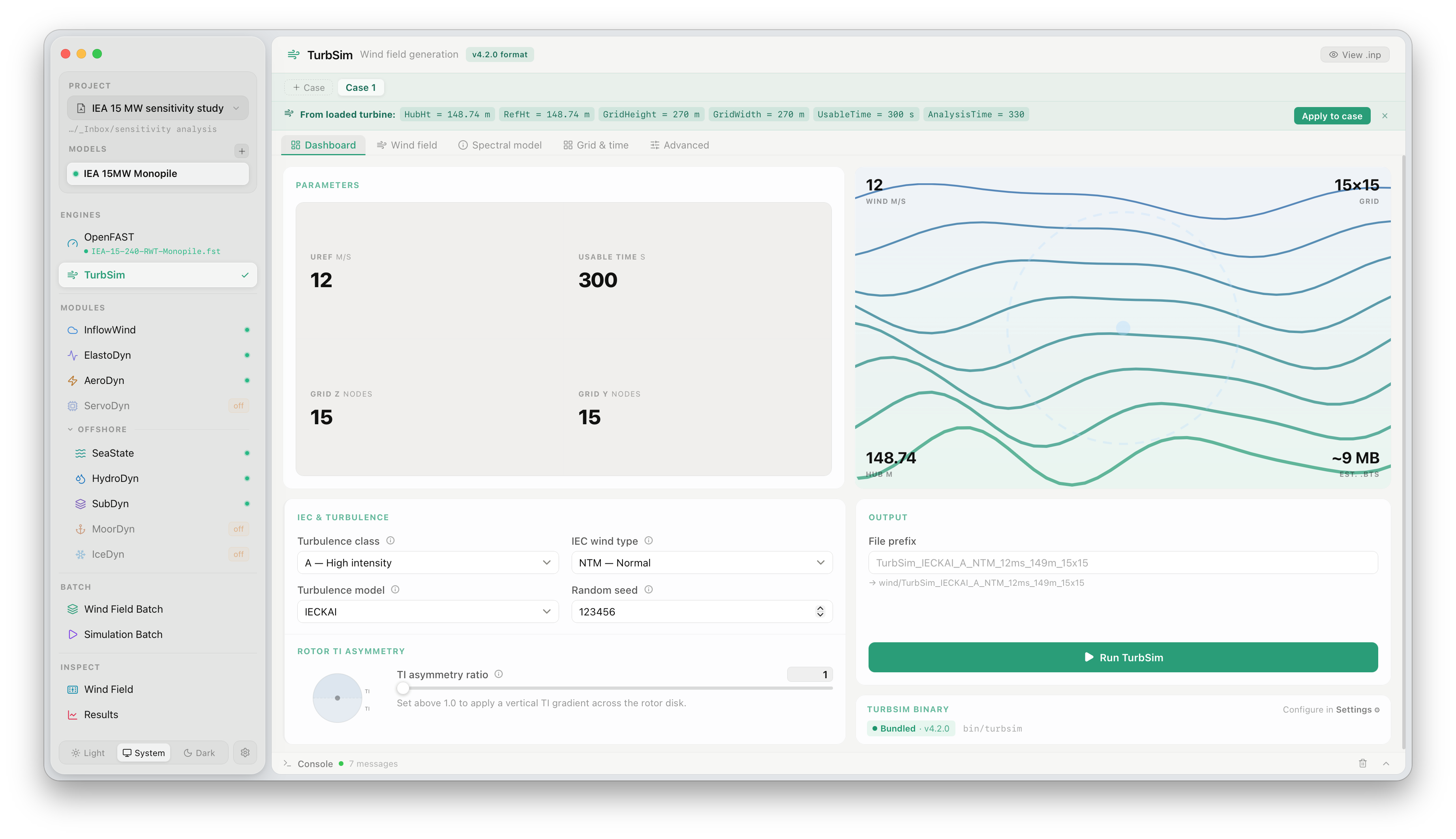
The panel is divided into two areas:
- Left — parameter controls organised into collapsible sections
- Right — a live wind field preview that updates whenever a
.btsfile exists for the current case
The header shows the bundled TurbSim version and a View .inp button that opens the raw TurbSim input file for inspection.
TurbSim supports multiple named cases within a single project, shown as tabs at the top of the panel (Case 1, Case 2, …). Each case has its own independent parameter set and generates its own output file. This is useful for comparing different wind conditions without using the full Wind Field Batch.
Click + beside the case tabs to add a new case. Cases are saved automatically in project.json.
Parameters
Section titled “Parameters”Wind speed and duration
Section titled “Wind speed and duration”| Parameter | Description |
|---|---|
| Wind m/s | Mean hub-height wind speed |
| TMax s | Simulation duration in seconds. Should be long enough to capture the lowest frequency of interest — typically 300–600 s for fatigue analyses |
| Num Z grids | Number of vertical grid points (rotor height coverage) |
| Num Y grids | Number of lateral grid points (rotor width coverage) |
A 15×15 grid (225 points) is the standard for IEC load calculations. Finer grids increase file size and computation time.
IEC & turbulence
Section titled “IEC & turbulence”| Parameter | Description |
|---|---|
| Turbulence class | IEC 61400-1 wind turbulence category: A (high), B (medium), or C (low intensity) |
| IEC wind type | NTM — Normal Turbulence Model. (ETM and EWM are available for extreme conditions.) |
| Turbulence model | IECKAI — IEC Kaimal spectral model. IECVKM — IEC von Kármán model |
| Random seed | Integer seed for the random number generator. Change the seed to generate statistically independent realisations at the same wind conditions |
Rotor parameters
Section titled “Rotor parameters”| Parameter | Description |
|---|---|
| Hub height | Height of the rotor hub above ground (or mean sea level for offshore). Automatically populated from the selected turbine model |
| Rotor diameter | Used to set the grid extent. Automatically populated from the model |
TI asymmetry (gTI)
Section titled “TI asymmetry (gTI)”The TI asymmetry parameter (gTI) controls the ratio of turbulence intensity at the bottom of the rotor disk to the top. A value of 1.0 (default) produces a uniform profile consistent with standard IEC NTM. Values greater than 1.0 apply a turbulence gradient that increases from rotor top to rotor bottom, reflecting the higher turbulence intensity found at lower heights in the atmospheric boundary layer.
See Gradient Turbulence Intensity (gTI) for background and a worked example.
Wind field preview
Section titled “Wind field preview”The right-hand panel renders a cross-section of the wind field for the most recently generated .bts file. It shows lateral slices of the u-component (along-wind) velocity at hub height, giving an immediate visual sense of turbulence intensity and spatial coherence. Key statistics are shown: mean wind speed, grid dimensions, hub height, and approximate file size.
The preview updates automatically after each run.
Output
Section titled “Output”TurbSim writes output to the wind/ subfolder of the project working directory. The filename encodes the key parameters:
TurbSim_IECKAI_A_NTM_12ms_148m_15x15_s01.bts │ │ │ │ │ │ └─ seed index │ │ │ │ │ └────── grid (NZ×NY) │ │ │ │ └─────────── hub height │ │ │ └───────────────── wind speed │ │ └────────────────────── wind type │ └────────────────────────── turbulence class └───────────────────────────────── spectral modelThe corresponding TurbSim input file (.inp) and summary file (.sum) are written alongside the .bts file for reproducibility.
Running TurbSim
Section titled “Running TurbSim”Click Run TurbSim. The button changes to a Stop button showing the case name, and the console panel streams TurbSim output in real time.

A typical run on a 15×15 grid at 300 s completes in 5–15 seconds on modern hardware. Longer durations or finer grids scale approximately linearly with the number of time steps and grid points.
Console output
Section titled “Console output”TurbSim reports progress through several stages:
Generating flow series for all points: u-component v-component w-componentComputing hub-height statisticsWriting statistics to summary fileWhen the run completes, the console shows the achieved hub-height turbulence intensity, which should match the IEC target for the selected class to within normal statistical variation.
Stopping a run
Section titled “Stopping a run”Click the Stop button at any time to terminate the TurbSim process. Partially written .bts files are removed automatically.
Using the wind field in OpenFAST
Section titled “Using the wind field in OpenFAST”After a successful run, the generated .bts file is immediately available in the OpenFAST panel. On the Dashboard tab, set Wind Source to BTS — FlowUrja Studio automatically detects and selects the most recently generated wind file for the current case. See OpenFAST Simulation for the next steps.
Applying to saved cases
Section titled “Applying to saved cases”The Apply to case button (top right of the panel) copies the current parameter set to one or more other cases, useful when only the random seed or wind speed differs between cases.