
OpenFAST Simulation
The OpenFAST panel is the central simulation hub. It manages the .fst primary input file, controls which sub-modules are active, configures wind input, and launches the OpenFAST executable. Click OpenFAST in the sidebar under ENGINES to open it.
Dashboard tab
Section titled “Dashboard tab”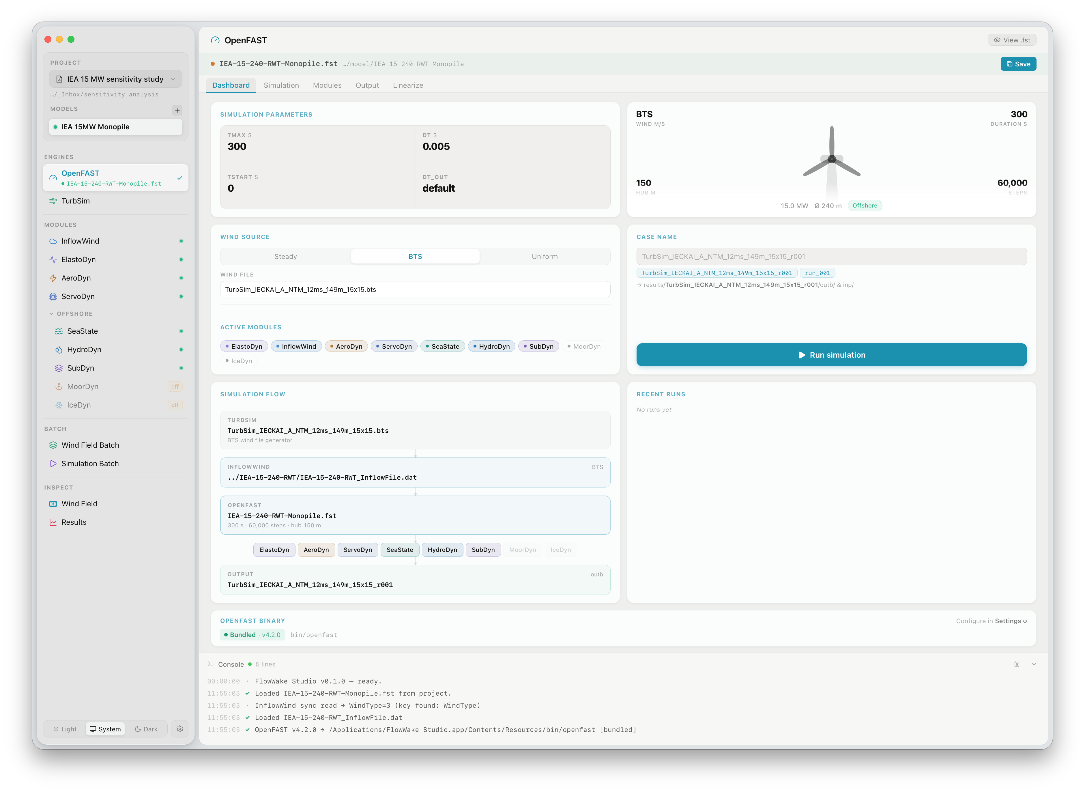
The Dashboard provides a complete overview of the simulation setup in a single view.
Simulation parameters
Section titled “Simulation parameters”| Parameter | Description |
|---|---|
| TMax | Total simulation duration in seconds |
| DT | Integration time step in seconds. The default of 0.005 s (200 Hz) is appropriate for most turbines. Reduce for stiff structures or high rotor speeds |
| TStart | Time at which OpenFAST begins writing output. Set this beyond the initial transient — typically 30–60 s |
| DT_Out | Output time step. default matches DT; set a larger value (e.g. 0.05) to reduce output file size without affecting simulation accuracy |
Wind source
Section titled “Wind source”Three wind input modes are available:
| Mode | Description |
|---|---|
| Steady | Uniform, constant wind at a fixed speed. Suitable for steady-state and power curve studies |
| BTS | Binary TurbSim wind file (.bts). Required for fatigue and load calculations |
| Uniform | Time-varying wind from a uniformly distributed wind file (.wnd) |
When BTS is selected, the Wind file field shows the active .bts file. FlowUrja Studio automatically selects the most recently generated wind file matching the current case. To use a different file, click the field and browse to any .bts file in your project.
Active modules
Section titled “Active modules”The coloured chips show all OpenFAST sub-modules currently enabled in the .fst file. These are set on the Modules tab and reflected here as a quick reference. Greyed-out module names are disabled.
Simulation flow
Section titled “Simulation flow”The Simulation Flow diagram traces the data pipeline from wind input to output:
TURBINE → IEA-15-240-RWT_InflowFile.dat (BTS wind file) ↓INFLOWWIND → InflowWind module config file ↓OPENFAST → IEA-15-240-RWT-Monopile.fst [ElastoDyn · AeroDyn · ServoDyn · SeaState · HydroDyn · SubDyn] ↓OUTPUT → case_name_r001.outbThis gives an at-a-glance confirmation that all file references are correctly resolved before launching a run.
Case name and output path
Section titled “Case name and output path”FlowUrja Studio automatically generates a case name from the wind conditions and a sequential run index:
TurbSim_IECKAI_A_NTM_12ms_148m_15x15_r001The run index (r001, r002, …) increments with each new run for the same wind case, preserving all previous results. Output is written to:
results/{case_name}/outb/{case_name}.outb ← OpenFAST binary outputresults/{case_name}/inp/ ← snapshot of all input files usedThe input snapshot in inp/ captures the exact .fst, InflowWind, and all sub-module files at the moment of launch, ensuring results are fully reproducible.
Turbine summary card
Section titled “Turbine summary card”The top-right card shows the key properties of the active turbine model: rated power, rotor diameter, hub height, offshore/onshore classification, and the total number of time steps at the configured DT and TMax.
Running a simulation
Section titled “Running a simulation”Click Run simulation. The button changes to a red Stop button and the console streams OpenFAST output in real time.
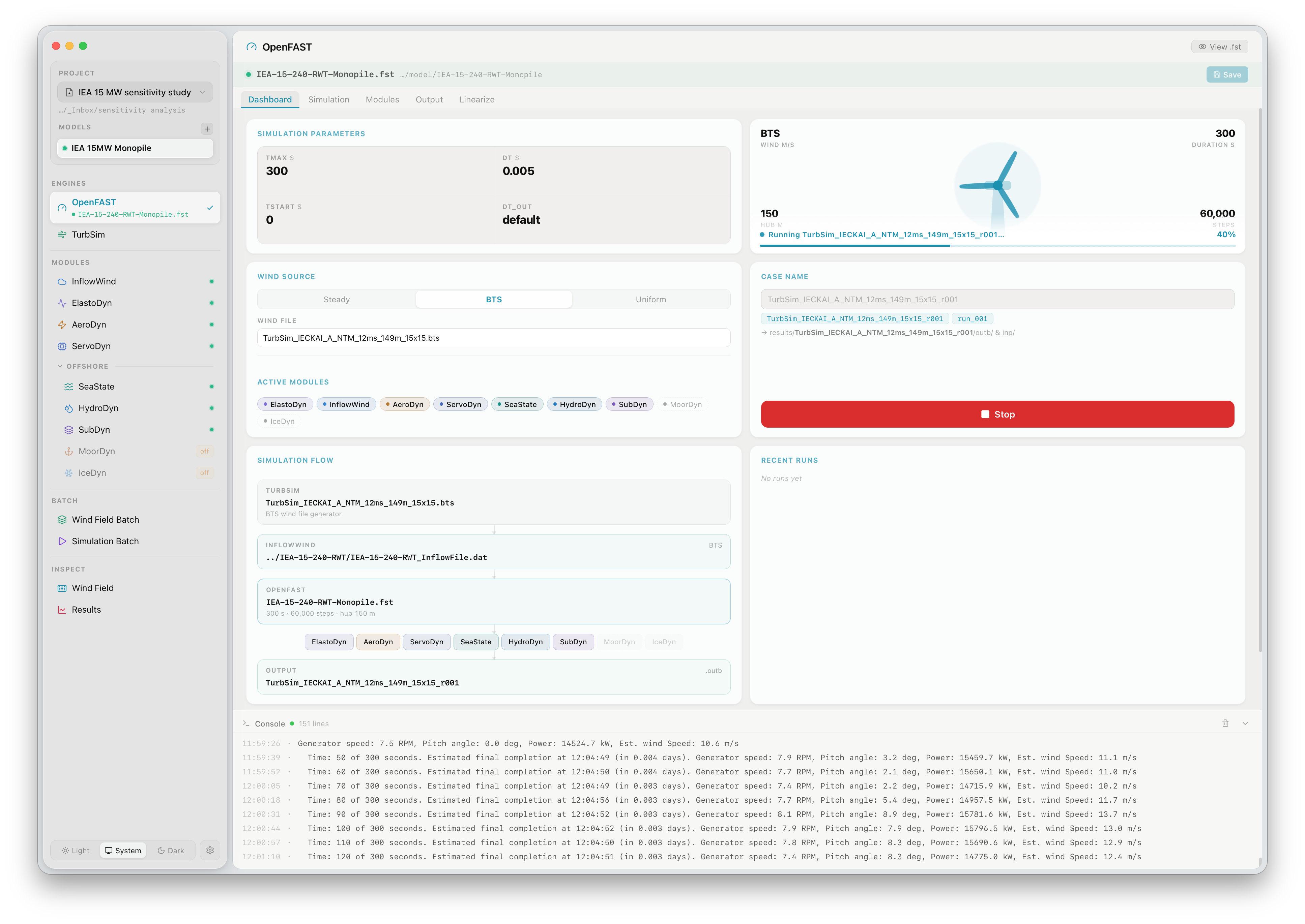
OpenFAST reports at every output time step:
Time: 10 of 300 seconds, Estimated final completion at 12:06:28 (in 0.480 mins),Generator speed: 7.3 RPM, Pitch angle: 0.0 deg, Power: 16453.2 kW, Wind speed: 11.4 m/sTypical run times for a 300 s simulation of a 15 MW turbine with full offshore modules (ElastoDyn, AeroDyn, ServoDyn, HydroDyn, SubDyn) are 3–10 minutes depending on hardware. Click Stop at any time to terminate the process cleanly.
When the run completes successfully, the case appears in the Recent runs list on the Dashboard and the output .outb file is immediately available in the Results viewer.
Modules tab
Section titled “Modules tab”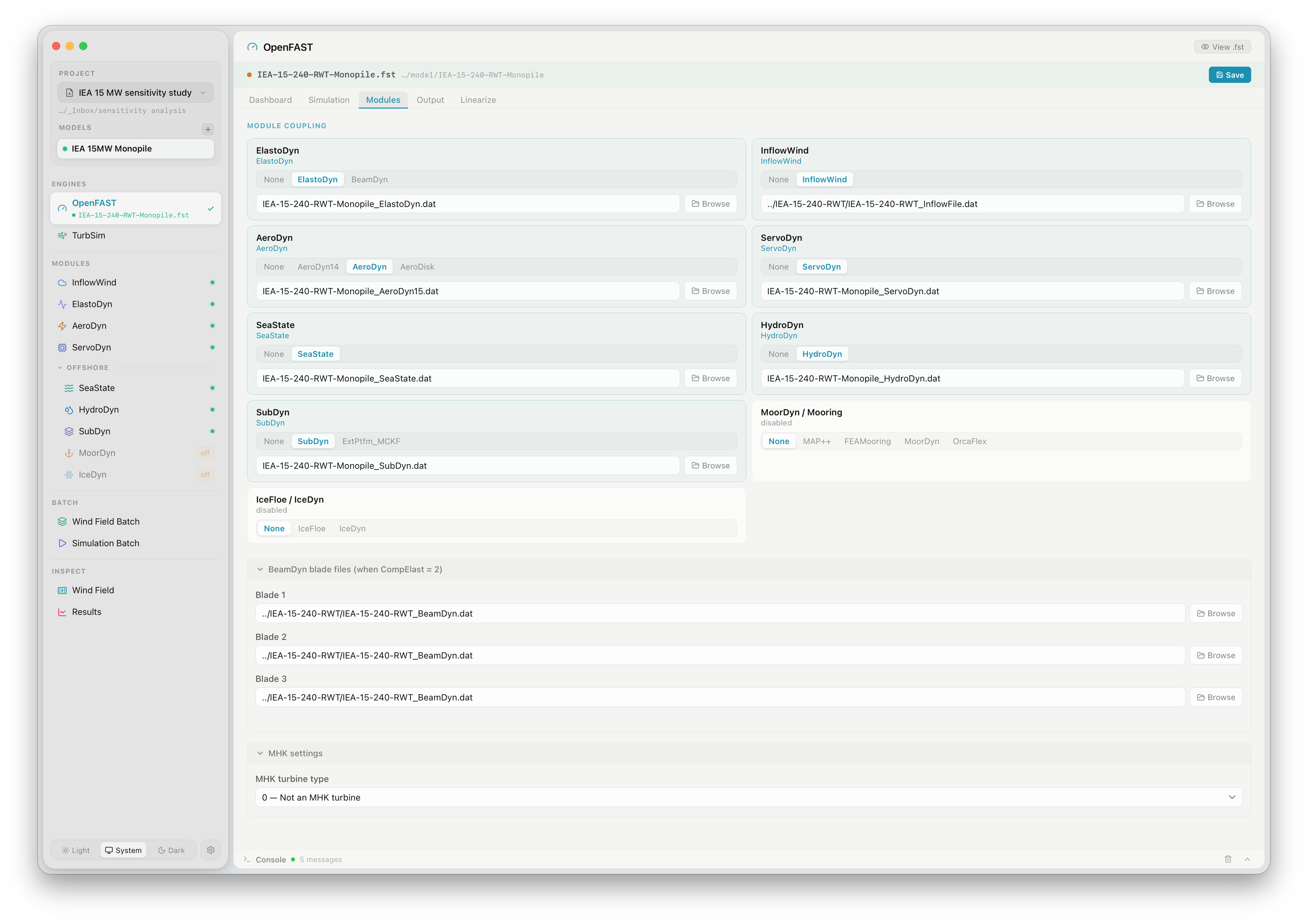
The Modules tab controls which OpenFAST sub-modules are active and which input files they use.
Module coupling
Section titled “Module coupling”Each module row has a selector for the implementation level:
| Module | Options |
|---|---|
| ElastoDyn | None · ElastoDyn · BeamDyn |
| InflowWind | None · InflowWind |
| AeroDyn | None · AeroDyn14 · AeroDyn · AeroDisk |
| ServoDyn | None · ServoDyn |
| SeaState | None · SeaState |
| HydroDyn | None · HydroDyn |
| SubDyn | None · SubDyn · ExtPtfm_MCKF |
| MoorDyn / Mooring | None · MAP++ · FEAMooring · MoorDyn · OrcaFlex |
| IceFloe / IceDyn | None · IceFloe · IceDyn |
Selecting None disables the module entirely (sets CompXXX = 0 in the .fst file). Selecting an implementation sets the corresponding CompXXX flag and activates the file path field below it.
Each active module shows the path to its input file relative to the working directory. Click Browse to select a different file. Changes are written to the .fst file immediately when you click Save (top right).
BeamDyn blade files
Section titled “BeamDyn blade files”When ElastoDyn is set to BeamDyn, three additional file fields appear for the blade structural input files (one per blade). These are populated automatically from the bundled model.
MHK settings
Section titled “MHK settings”The MHK turbine type setting (0 — Not an MHK turbine by default) activates Marine and Hydrokinetic turbine physics in OpenFAST when set to 1 (rotor above water) or 2 (rotor below water). Leave at 0 for conventional wind turbines.
Simulation tab
Section titled “Simulation tab”The Simulation tab exposes the remaining top-level .fst parameters not shown on the Dashboard: interpolation order, output format, linearisation settings, and the compiler/feature flags. These rarely need changing from their defaults for standard load analyses.
Output tab
Section titled “Output tab”The Output tab lists the channels currently selected for output in each active sub-module. Channels can be added or removed here without opening the individual module editors. Changes are written to the respective sub-module .dat files on Save.
Linearize tab
Section titled “Linearize tab”The Linearize tab configures OpenFAST linearisation runs (computing state-space matrices for control design). Enable linearisation, set the operating point wind speed, and specify the azimuth positions at which to linearise. This is an advanced feature — see the OpenFAST documentation for details.
Viewing and editing the raw .fst file
Section titled “Viewing and editing the raw .fst file”Click View .fst (top right of the panel) to open the raw primary input file in a read-only modal. This is useful for verifying that FlowUrja Studio has written the expected values. To edit parameters not exposed in the GUI, use an external text editor — FlowUrja Studio will reload the file automatically on next activation.