
Wind Field Batch
The Wind Field Batch panel generates a structured set of TurbSim wind fields by sweeping across multiple parameter axes simultaneously. It is the primary way to build the wind input matrix for fatigue load analyses and design load calculations (DLCs). Click Wind Field Batch under BATCH in the sidebar to open it.
Overview
Section titled “Overview”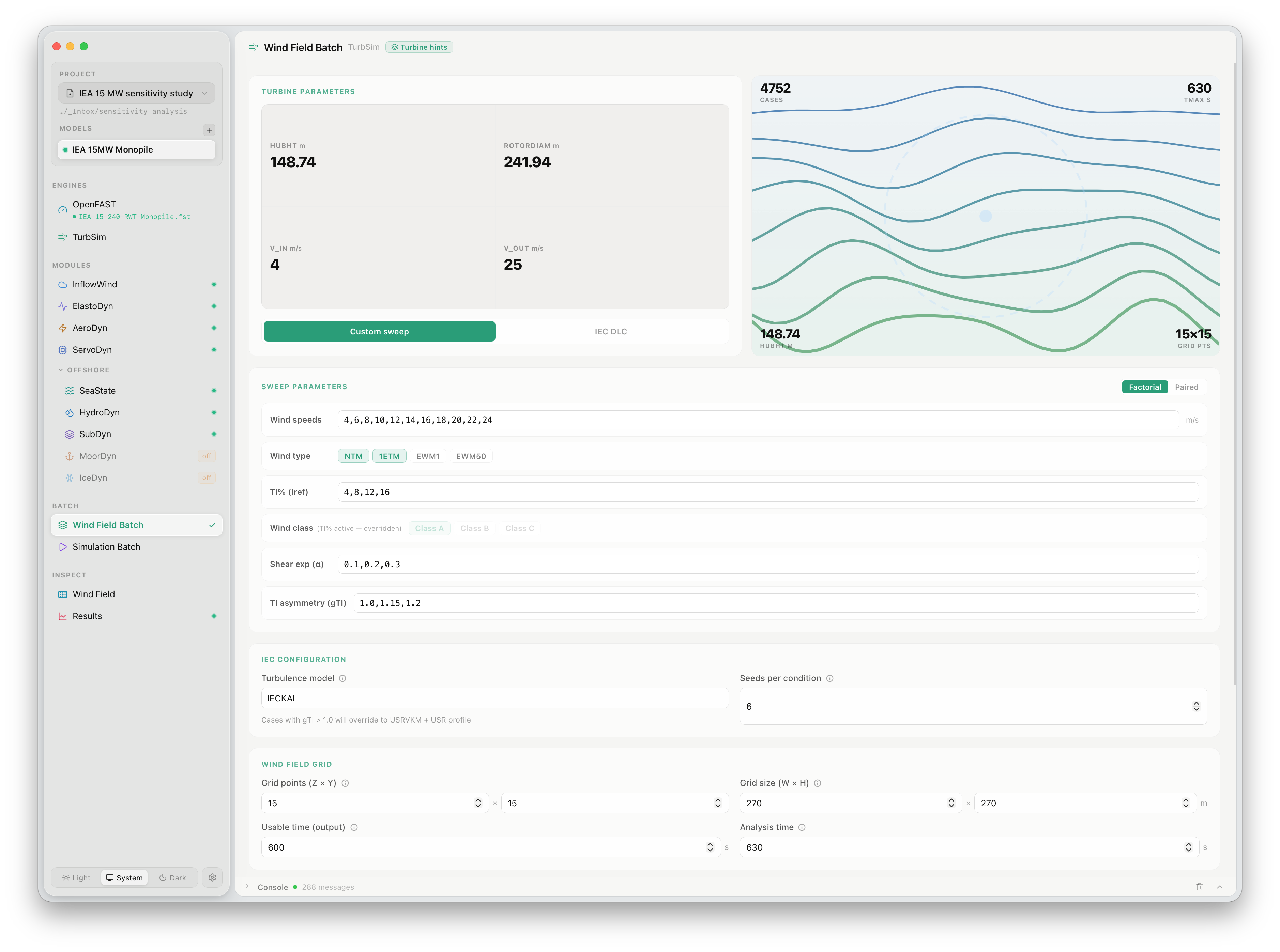
The panel is divided into three sections: turbine parameters (auto-populated from the active model), sweep parameters (user-defined axes), and grid/execution configuration.
The right side shows a live preview of the wind field for the most recently completed case.
Sweep modes
Section titled “Sweep modes”Two sweep strategies are available via the Factorial and Paired buttons at the top of the sweep parameters section.
| Mode | Behaviour |
|---|---|
| Factorial | Every combination of every axis value is generated. 11 wind speeds × 2 TI values × 3 shear values × 2 gTI values = 132 cases per seed |
| Paired | Axis values are stepped together in lockstep. All axes must have the same number of values. 5-element axes → 5 cases per seed |
Factorial mode is appropriate for full design load studies. Paired mode is useful when axis values have a physical relationship — for example, sweeping matched (wind speed, shear exponent) pairs extracted from site measurements.
Sweep parameters
Section titled “Sweep parameters”Wind speeds
Section titled “Wind speeds”A comma-separated list of mean hub-height wind speeds in m/s. For IEC NTM fatigue analyses, the standard range is 4–24 m/s in 2 m/s steps:
4, 6, 8, 10, 12, 14, 16, 18, 20, 22, 24Wind type
Section titled “Wind type”Selects one or more IEC wind condition types to include in the sweep:
| Type | Description |
|---|---|
| NTM | Normal Turbulence Model — standard fatigue loads |
| NETM | Not-extreme Turbulence Model |
| EWM1 | Extreme Wind Model, 1-year return period |
| EWM50 | Extreme Wind Model, 50-year return period |
Multiple types can be selected simultaneously; each becomes an additional axis in the factorial sweep.
TIs (ref)
Section titled “TIs (ref)”Reference turbulence intensity values in percent. These override the IEC class-derived TI and allow custom turbulence levels to be swept directly:
4, 8, 12, 16Wind class
Section titled “Wind class”Selects IEC turbulence classes (A, B, C) as an alternative to explicit TI values. When wind class is active, the reference TI for each class is derived from the IEC 61400-1 formula at each wind speed. Wind class and explicit TI axes are mutually exclusive — activating wind class overrides the TI field.
Shear exponent (α)
Section titled “Shear exponent (α)”Power-law wind shear exponent values to sweep. A value of 0.2 is the IEC standard for normal wind conditions onshore; 0.1 is typical offshore:
0.1, 0.2, 0.3TI asymmetry (gTI)
Section titled “TI asymmetry (gTI)”Turbulence intensity gradient across the rotor disk (see Gradient Turbulence Intensity). A value of 1.0 gives a uniform profile (standard IEC). Values above 1.0 apply an increasing gradient from rotor top to bottom.
1.0, 1.15, 1.2IEC configuration
Section titled “IEC configuration”| Setting | Description |
|---|---|
| Turbulence model | Spectral model: IECKAI (Kaimal, recommended) or IECVKM (von Kármán) |
| Seeds per condition | Number of statistically independent realisations generated for each unique parameter combination. A minimum of 6 seeds is required by IEC 61400-1 for fatigue analyses |
Wind field grid
Section titled “Wind field grid”| Setting | Description |
|---|---|
| Grid points (Z × Y) | Vertical × lateral grid resolution. Default 15×15 |
| Grid size (W × H) | Physical dimensions of the grid in metres. Should cover at least the full rotor swept area |
| Usable time | Duration of wind data written to the .bts file (the portion OpenFAST reads) |
| Analysis time | Total TurbSim simulation time, always slightly longer than usable time to avoid edge effects |
Parallelism
Section titled “Parallelism”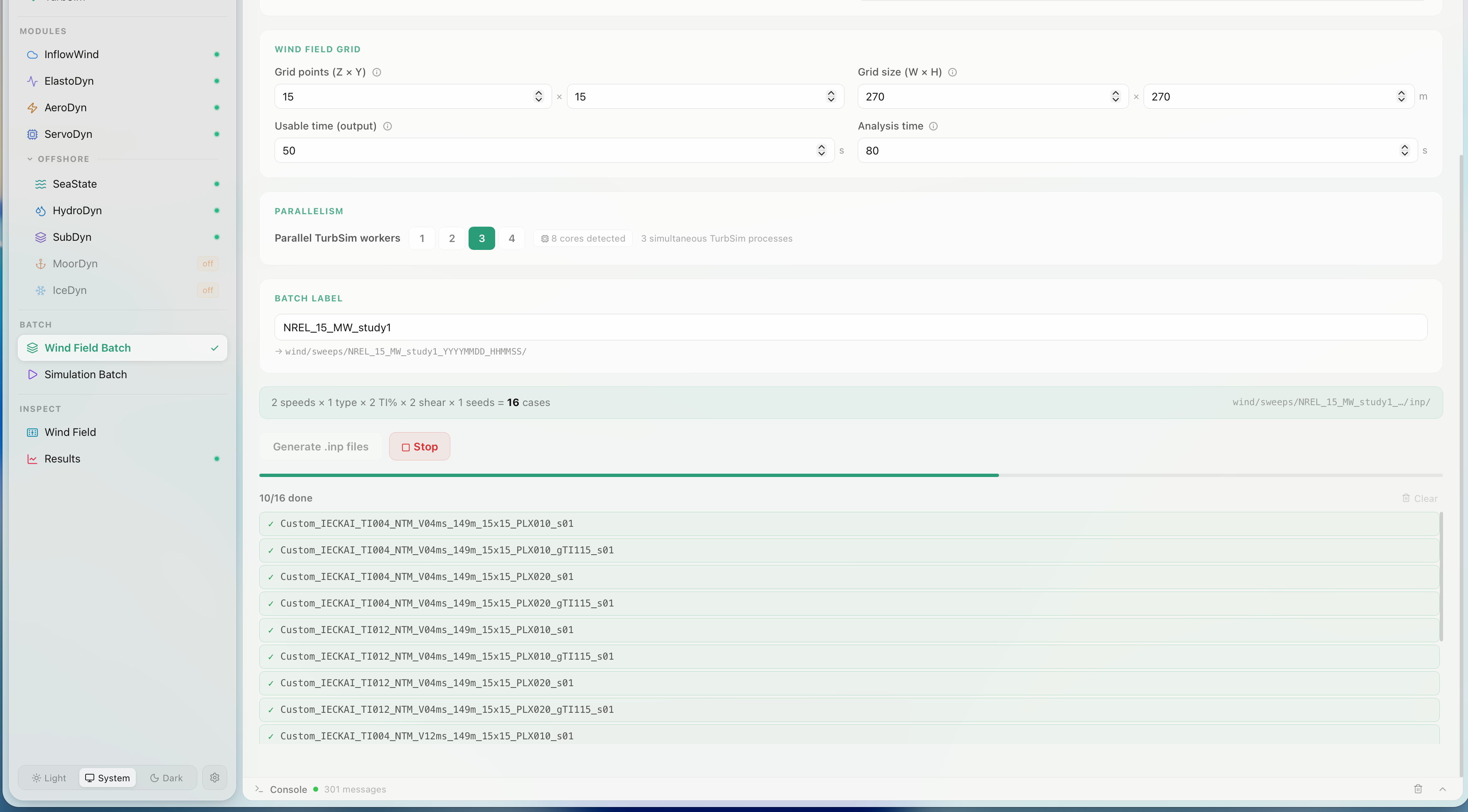
The Parallel TurbSim workers selector controls how many TurbSim processes run simultaneously. FlowUrja Studio detects the number of logical CPU cores and recommends leaving one core free for system tasks. For a 4-core machine, 3 parallel workers is the default.
Batch label and output path
Section titled “Batch label and output path”The Batch label is a short identifier for the sweep run (e.g. NREL_15_MW_study1). It appears in the output directory path:
wind/sweeps/{batch_label}_{YYYYMMDD}_{HHMMSS}/A timestamp is appended automatically so repeated runs with the same label never overwrite each other.
Case count and naming
Section titled “Case count and naming”The panel shows a live case count summary as you configure the sweep:
2 speeds × 1 type × 2 TIs × 2 shear × 1 seeds = 16 casesEach generated case file follows a systematic naming convention encoding all parameters:
Custom_IECKAI_TI004_NTM_V04ms_149m_15x15_PLX010_gTI115_s01.bts │ │ │ │ │ │ │ │ └─ seed index │ │ │ │ │ │ │ └──────── gTI (omitted when 1.0) │ │ │ │ │ │ └──────────────── shear exponent ×100 │ │ │ │ │ └────────────────────── grid (NZ×NY) │ │ │ │ └─────────────────────────── hub height │ │ │ └───────────────────────────────── wind speed │ │ └────────────────────────────────────── wind type │ └──────────────────────────────────────────── reference TI ×100 └─────────────────────────────────────────────────── spectral modelRunning the batch
Section titled “Running the batch”Click Generate .inp files to write all TurbSim input files without running them — useful for inspecting or archiving the input matrix. Click Stop (which replaces the run button when the batch is active) to halt at any point; completed cases are preserved.
During the run, completed cases appear in a scrolling list with green checkmarks. The batch can be stopped and resumed; already-completed cases are skipped on restart.
When all cases complete, the output directory is ready to be imported into the Simulation Batch panel.